Fresh Roast SR500 Coffee Roaster Computer

General Discussions about DIY Modifications and other projects.
SteveS
Site Admin
Posts: 25
Joined: July 15th, 2010, 3:03 pm

Re: Fresh Roast SR500 Coffee Roaster Computer

Post by SteveS »

Finally! I got the SD memory stick working! I managed to get it to create a CSV file on the SD memory stick with several (not currently populated) columns of data and a time/date stamp with a temperature reading from the thermocouple!

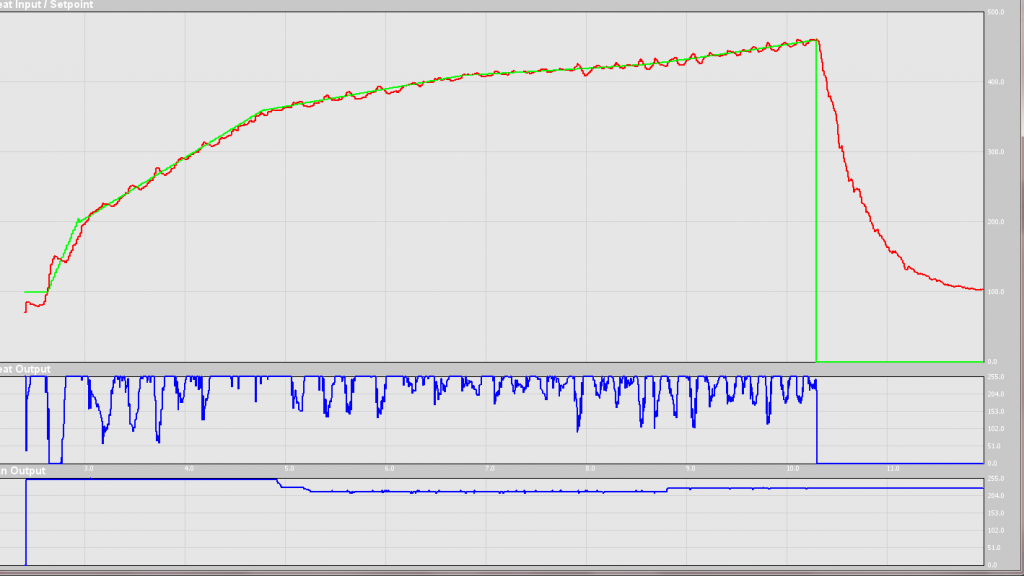
In about 4 minutes and 30 seconds that I just gave it a hit of heat and then let it cool (no roasting... just bare heat/cool cycle) it logged proper temperature numbers. During that time it did end up recording 2 readings per second with the occasional surge of 3 or 4 readings per second that I don't quite understand the variation. I guess there is something wrong with the way it is doing the timer so some places it squeezes in a little more while others it does not get in the full amount that is possible. Ultimately it should come out to 3 readings per second reliably but I'll need to read a other things along the way too eventually dropping it to 2 per second. Today it pulled 585 readings in 4 minutes 30 seconds.

Since I'm using the developer boards that have already wired up the graphics chip to a few pins that make life difficult :P I had to take the main data sheet PDF file and start highlighting the various pins for communication, then start placing boxes over some of the pin numbers that had graphics chip connections. THEN I printed it out and then started crossing off all the various pins that I have other sensors hooked to. I figured out I needed to move the USB com port over to a different set so that I could hook the SD memory to its own data bus separate from the other sensors. It compiled again and started up and worked like a champ immediately!

If anyone is looking to do something similar with the hardware I listed above at this time I have:

DS1307 on I2C number 1
FT232 on UART1 (blocks SPI3)
SSD1926 Graphics and LCD touch screen uses SPI2 which is a pre-built circuit board choice (I believe this is technically SPI1A) and the data pins for the SSD1926 blocks SPI1.
MAX6675 is on SPI2 as well
SD Memory is on SPI4 (aka SPI3A) (blocks UART 2 and 5)

Next step.... make the timing more reliable with the times per second sensor readings. THEN.... I'm gonna go roast something and log it!... probably do that this weekend.
SteveS
Site Admin
Posts: 25
Joined: July 15th, 2010, 3:03 pm

Re: Fresh Roast SR500 Coffee Roaster Computer

Post by SteveS »

Weird problem discovered... So for now I made a button to press to activate "first crack" tracking and then toggle it off at the end and then the same for second crack starting for roasts I drive into second crack. I pressed it for first crack at a particular temperature reading which I found in the log. It didnt say first crack next to it. Oddly it wasnt until MUCH further down the list after first crack was all over. It was actually off at that time and wasnt even "backwards" for any reason. The second crack notice on the roast was WAY down into the cooling phase and finished about 4-5 readings right before I pressed to stop the roast tracking. VERY odd.

it was very interesting to see the temperatures vs the wattage readings on the Belkin "kill-a-watt" type device that I had found recently. The whole roast it hovered around 1400-1475 watts mostly instead of the 1500 watt readings I was getting during an unloaded test. Randomly in the roast (probably when the little diode thing I found in the mesh opening up in the top part of the bottom roaster base would trigger an overheat) the roast would drop to around 900 watts "averaged" obviously and then lurch back up. I have a single 25 degree temperature drop that happened exactly the moment that the heater cut off the first time as evidenced by the watt readout.

I ran video of the wattage vs temperature readings so I can go back later and sync up times and temps and watch the wattage vs the data better and see what it comes up with. I also ran into a weirdism with this roast probably due to the coffee. It's from a sampler and I had not roasted any of this one before. The temperature probe was not aligned into my normal area so the temperatures seemed to run about 20 degrees hotter than I'm normally used to. This made it interesting trying to control the roast so I have more of a sweep than a series of sweeps and flattening points. I really need to do some kinda tripod video / webcam / etc so I can just pay attention to the readings and control the fan speed better for now.
Ira
Green Bean
Posts: 1
Joined: July 12th, 2011, 5:11 am

Re: Fresh Roast SR500 Coffee Roaster Computer

Post by Ira »

This looks like a great project, but I would like to start with something a little less complicated. Just some rough temp control to get the beans started drying more slowly. Do you have any wiring diagrams of the SR500?
SteveS
Site Admin
Posts: 25
Joined: July 15th, 2010, 3:03 pm

Re: Fresh Roast SR500 Coffee Roaster Computer

Post by SteveS »

I do not have any wiring diagrams of the roaster. However, I have an extra base that I am getting ready to disassemble sometime in the next week. While I'm taking it apart I will be photographing the breakdown. Think of it as what happens when a few of those tech blog guys get new iPads or iPhones and then strip 'em down. During the process I will probably take some voltage readings from a few spots I'm expecting to need to control or splice/replace.

Based on the way they built it from the last time I looked around inside one I may need to desolder a few things to get all the parts out. Check back for that being posted later in the month.

Update 7/18 - I have begun the process of taking it apart. I've separated most of the parts and they do come apart without desoldering. Assuming you pass wiring from below through a vent hole or drill the side you might be able to splice into the existing wiring probably. I still need to identify how the fans and heater use power to see if they are split or if one relies on the other at any time. Doing this you will lose the protection of the NTC.
SteveS
Site Admin
Posts: 25
Joined: July 15th, 2010, 3:03 pm

Re: Fresh Roast SR500 Coffee Roaster Computer

Post by SteveS »

Part One of the "FreshRoast SR500 Teardown" has now been posted in the blog HERE.

Part One discusses the basics of disassembling the SR500 coffee roaster and is focused on gaining access inside to allow someone to clean the inside.

I've photographed most of the circuit board removal and have one more board to finish for Part Two. I'm slowly assembling that into another blog entry. It will cover what is inside and what it's used for.

Part Three will end up covering electronic readings from various spots and a general discussion of the "flow" of electricity through the unit in terms of AC/DC, logic and how the sensors/controls cause things to happen in the system. I'll also need to wire up a few things to test separating fan and heater and try to get readings from the NTC for people that would want to build a new "brain" for their roaster. In that part I'll try to figure out just how much can be unplugged from the roaster before you have to entirely replace everything for the brain.
SteveS
Site Admin
Posts: 25
Joined: July 15th, 2010, 3:03 pm

Re: Fresh Roast SR500 Coffee Roaster Computer

Post by SteveS »

I posted a second blog entry showing more photos and explanation of taking things apart. I've got some parts on order for trying to control the heater with a TRIAC and a zero-crossing detector. This is where you sense when the 60hz wave of the AC power momentarily becomes 0 volts. It then sends a signal to the microcontroller which starts a timer. Once this gets going it "switches" the electricity on and off based on what amount of power you want to get to the heater element.

In the second blog I'll be updating it to show more information about what sort of voltages come from specific parts that I will test as I disconnect things and "bypass them" with new circuits. The modifications will be discussed more in a third blog about taking it apart and then more so about "putting it back together".

I've also purchased some software called "VGDD" that assists in designing screens. I've been working on building some of the 800x480 dimension screens for the new touch panel. I've got an area (guessing) around 600x300 that will be used as my real-time roasting curve display. Two sliders on the screen will be used to control the dimmer circuitry to adjust power. I have to figure out how i will "build my automated profile" profile builder and the way to run it of course. For now setting up a roast for manual control and showing the info is the goal.

Once I get the TRIAC's switching the power on and off to a socket (and safely mount it into a box so I don't accidentally get shocked) I'll have to work on the timing and then interface that to the control system. I won't be doing that until the large screen is fully functioning with the roaster software. So far I've had demos running on the big screen and roaster on the little one. I have to convert the drivers for the large screen driver chip over to the new graphics library version I used for the roaster.
SteveS
Site Admin
Posts: 25
Joined: July 15th, 2010, 3:03 pm

Re: Fresh Roast SR500 Coffee Roaster Computer

Post by SteveS »

Unfortunately it seems I accidentally left off the TRIAC driver from my last order. I now have the TRIAC, a zero cross detector, a bunch of bags of resistors, heat sinks, lots of sockets for power to be fed into and out of a case for both heat and fan separately, spools of wire to run power in and out of a board, various blade quick connects to match the internal wiring, some DC fans for cooling the case until I'm sure of the sizing of everything and a variety of other random bits. I also obtained some items to etch a board. I figure I should start with "coarse" wiring before I really get into the finer SMD stuff. I think I've finished an Eagle layout to make a decent board to control all of this. I need to adjust the size of the traces to handle the electrical load after researching that more and then get my board material and try it out. I'll probably make a physical prototype using wire and lots of heat shrink and other clunky bits first to ensure I don't melt anything and then go for a board afterwards.

I've also decided to get an arduino board to use to "verify" sensor boards using sample sketches to ensure my sensors are in proper working order since almost all of them have samples that use Arduino available while only about 1/4 of them had code for PIC32 and I've written code for another 1/4 of them. I have yet to get my ambient air temperature sensor to so much as say boo connected to the PIC32 but I'm pretty sure it actually works. I just need to verify on the Arduino first before I get more "Agressive" with it. The remaining 1/2 of my sensors still need custom written code to be produced and I'd rather see it work on an Arduino first before I wire it up to the PIC32 and try to convert it just to be sure I didnt get a "defective sensor".

I'm pretty sure I won't use it long term but I was "entertained" by the motorized sliders for sale at SparkFun. These are similar to the sliders used on mixers like used on a ProTools Project Mix I/O where you can move them automatically to a preset position and then slide them manually to the appropriate position. I will likely draw these on the screen and then make the physical slider control the on-screen slider which then controls the actual roaster settings. Pre-set profile programming can then slide the physical sliders to the desired position automatically as required. It's "really geeky" but mainly for bling rather than REAL function. Everyone loves watching sliders move around by themselves and control stuff.
SteveS
Site Admin
Posts: 25
Joined: July 15th, 2010, 3:03 pm

Re: Fresh Roast SR500 Coffee Roaster Computer

Post by SteveS »

Ran into a weird problem with the VGDD software. All the sheets I've made don't want to compile. Any of the text seems to fail to compile unless I modify the way it builds the text. I'm not sure why I have to do that for my projects while other people don't normally have those sorts of problems. I've been talking to the author about it and will need to compile a projectagain after creating a good test project that is stripped down a little more. I've gotten other text to come up in tests but none generated with the VGDD software. No idea why this happens but it seems to do it compiled under XP and Windows 7 with the current (until a few days ago when a new version came out) compiler.

There might be an issue with one of the peripheral libraries or something that freaks out but I'm not really sure. I'm pretty sure I can still use the output regardless even if I have to replace some stuff to get it running.

I've now succeeded at testing yet another temperature sensor. Tomorrow I have two more boards I need to solder up and test out to ensure they work on the Arduino first. This temperature sensor seems a lot more accurate than the other one I tested last night. It also has humidity on it which also seemed reasonably accurate. Time from wiring it to getting code written and working to check it? 10 minutes maybe on the Arduino. I spent hours trying to get it talking on PIC32 and never got good data out of it. With the Arduino it's spitting out data in minutes.
SteveS
Site Admin
Posts: 25
Joined: July 15th, 2010, 3:03 pm

Re: Fresh Roast SR500 Coffee Roaster Computer

Post by SteveS »

Still working on the Arduino. I've ended up integrating PID code into the Arduino and have it running to a Serial text LCD and to a Processing sketch that graphs it on the computer screen in real time. I ended up getting a box at radio shack and wired up a TRIAC based dimmer and then connected the power sockets into the case, screwed the board down in the case, built a board that accepts all of the wiring from a DB25 and then sends some of it to the TRIAC board and then has a socket that goes up to a control panel with the LCD, potentiometers, several LEDs showing Auto/Manual control and varies the LED output on another pair to show level of heat/cooling being applied. Will be working this weekend to get the SD logger going and then I'm gonna start testing. The Arduino sits outside of the RadioShack case. The controls and LCD and the dimmer capabilities are sealed up in the box so that the high voltage is protected and the "mass" is used for a stable base to mount those controls on. The interface is then somewhat "universal" so that I can convert it to PIC32 next without having to open up the case to change anything.
SteveS
Site Admin
Posts: 25
Joined: July 15th, 2010, 3:03 pm

Re: Fresh Roast SR500 Coffee Roaster Computer

Post by SteveS »

So it's been a while since I updated this post. At this time I've managed to get the Arduino fully controlling the roaster by itself. I need to add some buttons to give it an automatic turn off the heater and run the fan on high capability and eventually allow me to add customized roasting commands and target temperatures manually. The processing software reads the data from the Arduino in real time and draws a graph. The most recent roast came up like this.

Image

The accuracy of the temperature tracking is still not good enough because the PID needs to ACTUALLY be tuned properly. The current settings were based off of some "trial and error" guessing.

Internally the guts look like this:

Image

Mains power comes in on the left side into a standard PC type "D" plug with a power switch on it. It enters the board on the lower left which has the sensing chips for zero cross and the triacs and trigger chips to send power to the fan and heater. Low voltage wiring is down below and leads to the board on the left with some Resistors and a ribbon cable connector that goes up to the control panel. The wiring leads back to the DB25 to return to the Arduino. There are two standard power sockets coming out from the back side. One of them goes to the heater and the other is actually plugged to the transformer. Due to issues I had with the fan circuit in the roaster I had missed the fact that there was a heater coil before the fan used to drop the effective voltage down to a lower number. It then converted that to DC electric and powered the fan. Now I'm using the transformer to convert from 120vac down to around 25vac and then using the triac to deliver variable amounts of power to the transformer. The original bridge rectifier converts the AC to DC like normal. Had I caught this earlier I would have used a non AC power socket for the fan side. Additionally the socket I used is designed for a thinner enclosure so it doesnt fit as well as I'd like due to the ridges in the radioshack case that are spread across the walls. These ridges are for being used as guides for PCB's to be installed straight down into the case (in a "card" configuration) instead of being screwed to the bottom.
Post Reply