I've tried having a laser cut case made to put the roaster controller into. I've thrown together some pieces to move forward with it a little more and try to keep it all more self-contained as I progress. Initially it seemed to make sense to try to create a button board which I sent off to OSHPark.com (formerly DorkbotPDX PCB) and mount it and a LCD to my panel. I attempted to create a panel that will migrate to the newer models as I get further along. The first button panel was made to minimize wiring so it chains all of the buttons together using resistors to signal which button is pressed to the analog line on the arduino. This is due to the Arduino still being outside of the case connected to the back.
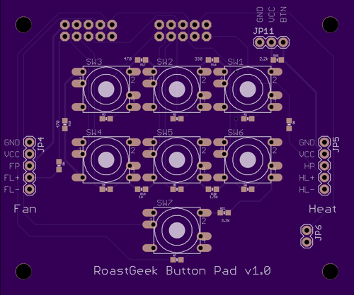
Version 1 of the button board is as follows:
Button Side
Bottom Side
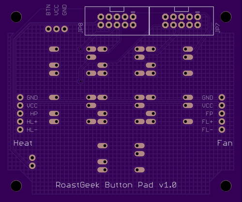
As the project continues I will replace the button board with other variations that will have different wiring harnesses coming off leading to newer main boards. These would be to have more wires so that each pin could be individually monitored and then as I get further along I will probably wire up some sort of "intelligent" board that would buffer binary on/offs for each of the buttons and send it all at one time to the microcontroller. Since there are 7 buttons it could technically transmit any combination as a 7-bit ascii over any sort of bus back to the controller.
Getting back to the case I feel laser cutting allows me to create an opening for the 7 inch LCD and then create an insert that fills the opening that uses "friction" to hold it in place. This seems like it should do well enough for the time being. The insert will house the 20x4 LCD text screen that I am currently using on the Arduino side. When I get further along and am back to including some of the PIC32 functions I will adapt the touch screen back in place. At that time the finished product would look something like this:
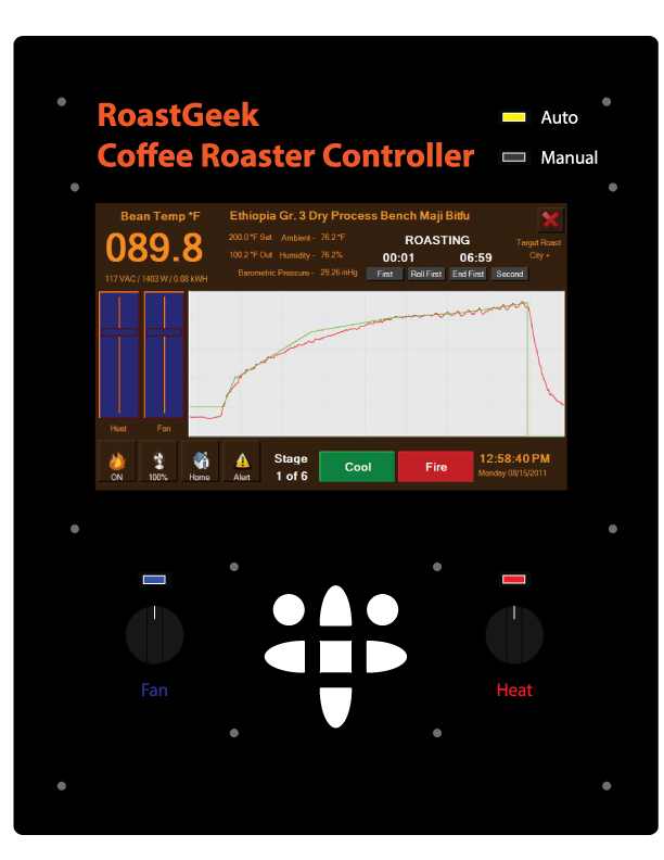
I ordered some plastic for gluing the corners together and screwing other pieces together which has already arrived. Right now I am waiting for some attachments to put on the bits I'm using to allow me to countersink the screw holes somewhat. Once these arrive I will be able to test fit all the parts together and make a few adjustments in some of the measurements and positions. At that time I will order a new version of the controller case.